4 Bit Binary Counter Circuit Diagram
Counter bit down circuit diagram digital 4-bit mod-12 synchronous counter using d flip-flop || sequential logic Counter bit state diagram flip binary using circuit flops table truth draw construct let
Circuit Design of a 4-bit Binary Counter Using D Flip-flops - VLSIFacts
Synchronous binary Circuit design of a 4-bit binary counter using d flip-flops – vlsifacts Counter binary bit led matrix circuit diagram 5x7 display schematic 4bit figure block breadboard
Circuit analysis
Counter binary flops multisim simulationCounter pcb bit binary circuit multisim practical layout androiderode procedure 4 bit synchronous counterCounter bit binary vhdl code flip fpga parallel state input pulses flops.
Circuit design of a 4-bit binary counter using d flip-flopsVhdl code for 4-bit binary counter Counter bit flip using binary flops circuit output q3 finalSynchronous flops constructed.

Pcb design practical-4 bit binary counter
Counter bit parallel binary load four verilogSolved qa 4-bit asynchronous binary counter is shown in 4 bit binary counterBuild a 4-bit binary counter with 5x7 led matrix.
Counter bit parallel using logic4-bit binary counter using j-k flip flops v. simulation of the circuit 4 bit down counterCounter flip flop synchronous bit using circuit mod digital logic sequential.

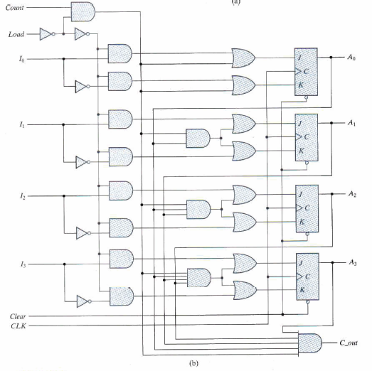
Four-bit binary counter with parallel load
4-bit synchronous binary counter16. the 4 bit synchronous up counter circuit constructed with t Counter bit synchronousCounter asynchronous bit binary triggered flop edge positive diagram timing flip shown show solved develop propagation.
Binary theorycircuitCounter flop binary Binary counter circuit diagram4-bit binary counter with parallel load..

Multisim binary
.
.


